
You will also have to multiply the Easting and Northing by 1000 to take into account the scale difference between the Survey (in Meters) and the Revit Project (in Millimetres). You should never unclip and move the Project Base Point as this can affect IFC datum and coordination with other models.Ĭoordinates can be given from either the Project base point or the Survey Point. You could also leave the Survey Point at 0,0,0 which would be the OS False Origin. Note that in the above example the Survey Point was unclipped and moved to the Station ‘ST1’.

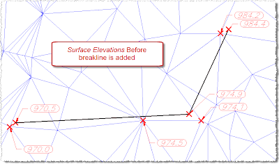
An example may look similar to the image shown below. To ensure correct coordination to Revit you should clearly mark a survey station that you would like to reference and also a project base point. Select the Display tab, make sure that the View Direction is set to Model and ensure that Triangles are visible and all other component types are switched off. To ensure that AutoCAD Civil 3D is showing triangles, select the Surface and then select ‘Edit Surface Style’ from the Right Click context menu. The points are connected in a different order and can cause minor differences in levels. In the image below the Revit Triangulation algorithm is shown in red. In the example below you can see a triangulation model from AutoCAD Civil 3D with the points shown in red and the levels shown in blue. In practice you should create the Revit Surface directly from the AutoCAD Civil 3D triangles.

This could potentially allow errors to creep in if we simply rely on points and use these points to build surfaces in Revit and Civil 3D. In this first post I will concentrate on the fundamental task of getting a TIN (Triangular Irregular Networks) surface from AutoCAD Civil 3D to Revit as a 3D TOPO.ĪutoCAD Civil 3D and Revit each use slightly different algorithms for the triangulation of surfaces.


 0 kommentar(er)
